Thursday 25 June 2009

It’s been a long time since the last update but not because the build has halted… I’ve had my viva and got some letters (PhD), Dr Will still sounds strange! The write-up period ended up giving me a dislike of typing and computers in general so I’ve been keeping busy in the garage.

The correct sump baffle arrived quickly and is now installed. I’ve also got a new oil filter, have held off on fitting this as I may be getting a sandwich plate (between engine block and filter) to accommodate the oil pressure and temperature sensors.

Rivnut tool


I’ve made a rivnut tool for the larger size rivnuts, the tool I bought is only capable of <>


The end result used for installing M8 rivnuts:


1x M8 hex key 1x M8 cap head bolt

1x ali strip (2 mm) ~15 cm long (with suitable holes)


1x M8 nut (nyloc)


1x M8 washer


1x spanner


After a couple of practice attempts I was happy with how it worked, giving a nice even crush on the rivnut. I then installed the rivnuts for the pedal box.


Fuel system


Tank


The tank will be secured using the tank straps (made earlier) and rivnuts in the tank support brackets (also lined with foam).


Vent valve

To allow air in and out of the tank (equalise pressure) and prevent fuel escaping in the event of a roll. I’ve fitted a tank breather valve to one of the pipes from the top right of the tank (next the return pipe). This needs to be mounted vertically so I used a short length of the narrower fuel pipe, from the original bike fuel return, straight onto the vent port.


Pipe work

I’ve re-routed the return line so that it clears the mounting plate for the Quaife reverse box. All the 8 mm copper fuel lines have been secured with p-clips every 10 – 12 cm. The ends of each pipe were flared to give a good seal against the flexi lines when clamped with fuel hose clips.


Reusing R1 connector


For attaching the fuel supply fexi hose to the fuel rail I reused the original releasable joint. This just required removing the original supply line (easily trimmed off).


Sender
The sender unit needed positioning so when mounted to the top right of the tank with the float was near central, moving freely and would engage the switch before reaching the bottom of the tank (to give some reserve once warning light is on). This took a bit of thinking to get the correct bend in the float arm.


Filter

I’ve fitted a clear plastic free flowing fuel filter, so I can keep an eye on what’s going on. This is located between the tank and fuel pump.


Pump

To fit the fuel pump I’ve made a bracket from 2 mm ali strip lined with foam strip. I mounted this left of the diff with a rivnut in a chassis rail.
More photos of the fuel system install to follow, plenty of other bits have been done but thats enough computer time for now....

Monday 13 April 2009

March-April 09


I’ve managed to get a few bits done since submitting the thesis and getting my viva out of the way. The rear brake lines have been routed up the transmission tunnel and fixed using p-clips (gaps <>


Over the Easter bank holiday weekend I had planned to fit the baffle plate into the sump. Unfortunately once I’d drained the oil and got into the sump it was quickly obvious the hole pattern on the baffle was not going to fit. The oil pick-up tube and oil strainer had to be removed, the baffle inserted and then the pipes reattached to hold the baffle in place… not possible with this hole pattern.

A quick call to Malcolm at Yorkshire engines confirmed I have the wrong baffle.
The next job I tackled was fabricating a pair of petrol tank straps from two ali strips and some sticky backed foam strip. I bent the ali to fit, stuck the foam to the side contacting the tank and drilled holes at either end for bolting to the tank support brackets (also faced with sticky back foam).


Whilst doing the fuel system I started routing the 8mm copper fuel pipes (with correct markings), this is much trickier than the brake pipes, being much thicker! I’m not entirely happy with the routing as it stands, shall probably have a think and have a second attempt.


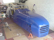
A couple of other things I’ve been working on are the pedals, now with bright blue grip tape trimmed to fit (looking sharp I think) and some additional M8 bolts holding the pedal box to the floor. I also got all the bodywork out and put it together to see how it looks, nice!

Sunday 15 February 2009

Thesis submitted: build progress


Well it’s been a slow time in the garage of late due to getting a full time job (Research Scientist) playing with bioreactors (fermentors) and writing up my PhD. However, the Thesis is now submitted with the viva coming up in early March so I am getting my life back!


When I have been able to get out the spanners over the Christmas period I managed to get the driver side bulkhead fitted (Siklaflex and rivets) and the passenger side bulkhead trimmed and ready for fitting.

The pedal box has been trial fitted and I’ve bought some bright blue skateboard deck grip tape to put one the pedals. I’m planning on putting the icons for the controls (Throttle Brake, shift up/down etc.) from GT on the Playstation on each of the pedals.

Since submitting I’ve got the front brake pipes routed and fixed (p-clips and 3.5 mm rivets) with a spacing of 120 mm (maximum 6 inch spacing for SVA). The front brake T-piece was attached to the chassis and the brake pressure switch was installed.

So the pedal box could be fitted, holes had to be drilled through the bulkhead to accommodate the master cylinders (front and rear) and 4x M8 bolts for mounting the pedal box. The dremmel style tool came in very handy for fettling the large MC holes.

I’m hoping to get the remaining brake lines routed and fixed in the next few weeks depending on how my viva preparation goes. Finger crossed!